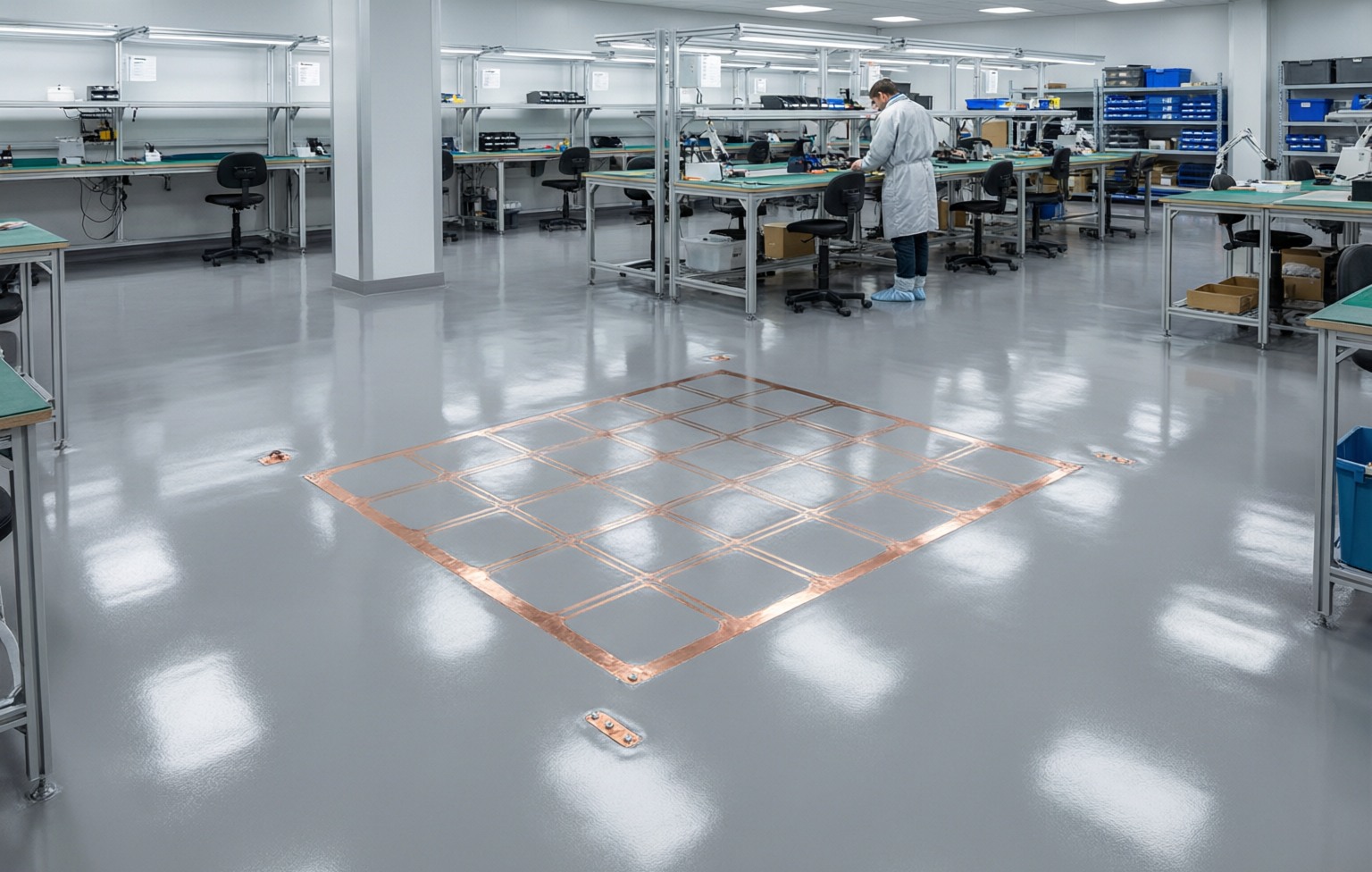
Earthed copper grid pattern visible beneath an anti-static epoxy floor in an electronics workshop

ESD Epoxy Flooring Specification — What You Actually Have to Get Right

Anyone selling this product can quote you a resistance number. The number is the easy part. A floor passes on paper and fails in service because nobody specified the earth path, the test points, or the footwear that would stand on it — so this page is about the parts that decide the outcome.

2Resistance bands in normal use
3Measurements at handover
16+Years manufacturing
40+Countries exported

Two bands, and the difference is not performance — it is speed

Conductive and static-dissipative are not "better" and "worse". They discharge at different rates, and which one you want depends on whether a fast dump protects the process or damages the device. Anything above 10⁹ Ω is not either band — it is an insulating floor that happens to have been sold as anti-static.

Conductive

10⁴–10⁶ Ω

written on supplier sheets as 10^4~10^6 ohm

Areas where a charge has to leave fast: explosive and flammable processing, hydrogen and solvent handling, munitions, some semiconductor diffusion areas.

Shunts a discharge quickly, which is what you want for ignition risk and what you do not want next to a device being handled — a fast dump can itself damage the part.

What we supply

Static-dissipative

10⁶–10⁹ Ω

written on supplier sheets as 10^6~10^9 ohm

The band most electronics assembly, SMT, test, server rooms, imaging suites and pharmaceutical packing actually specify. Charge leaves, but gently enough that the floor is not the event.

Slow enough that a genuinely high-ignition-risk area is not covered by it — that is what the conductive band is for.

Insulative (the failure mode)

above 10⁹ Ω

written on supplier sheets as > 10^9 ohm

Not a specification — a diagnosis. A standard sealed epoxy floor, or an ESD floor that has been waxed, sits here.

Nothing to trade off: at this resistance the floor is holding the charge it was supposed to remove.

Both ranges are quoted as a design target for the finished floor, measured on your slab against an earth-point log — not as a factory certificate. Anyone who ships you a certificate for a floor that has not been poured yet is certifying the ink.

Three measurements decide handover

A single "surface resistance" figure is the one most specification sheets ask for and the one that hides the most. These three answer different questions, and a floor can pass two of them and still be useless.

Commissioning measurements for an ESD epoxy floor
What is measuredWhat it readsWhat it catchesWhen it fails, the usual cause
System resistance to earthFloor → earth terminal, through the whole conductive pathWhether the grid is actually bonded. A floor that measures fine point-to-point but fails here has a broken earth, not a broken topping.Missing or unbonded earth point; grid laid but not tied to the terminal; terminal painted over during finishes.
Point-to-point resistanceTwo points on the finished surface, same zoneWhether the surface itself is continuous. This is the number a supplier sheet usually quotes, and it is the one that can pass while the floor still fails commissioning.Construction joints left unbonded; a patch repair done in standard epoxy; wear coat applied over an insufficient conductive layer.
Person-to-floor / charge decayA person standing on the floor, in the footwear they will actually wearThe only one of the three that describes the real system. A perfect floor under a person in insulative shoes still builds charge.Footwear not specified alongside the floor; trolley castors replaced with standard ones after handover.

We do not print standard numbers on this page. A resistance band without a test method attached to it is a decoration, and a supplier who names a standard they have not been tested against is worse than no number at all. Specify the measurements above with your own ESD consultant, and we will build to them and log the results.

The build-up that carries the current

Conductivity in this floor is a property of the whole stack, not of one component. Every layer below the wear coat is part of the path, which is why the quantities are published rather than described.

Layer quantities

  • Conductive primer0.2 kg/m²Carbon-loaded
  • Copper grid200–600 mm meshBonded to earth points
  • Anti-static topping2.2 kg/m² per mmPoured 2–3 mm
  • Conductive wear coat0.25 kg/m²
  • Earth terminals≥ 2 per 100 m²Resistance logged at handover

Application and cure

  • Mix ratioA:B = 4:1 by weight
  • Pot life30 min at 20 °C
  • Foot traffic8 h
  • Full cure7 days at 20 °CLight service at 24 h; performance tests read after full cure
  • System resistance10⁶–10⁹ ΩDesign target; measured on the finished floor against an earth-point log
  • Working conditions10–30 °C, RH ≤ 75 %Sound concrete ≥ C25, substrate moisture ≤ 4 % (CM test), ambient 10–35 °C and relative humidity ≤ 80 %, surface at least 3 °C above dew point.

Figures are typical values measured in our laboratory. Substrate, climate and workmanship affect the result — we confirm the final specification in writing before your order.

Five things that break an ESD floor after it passes

These are not hypothetical, and in most cases the floor material is fine — what failed is the path. This is the section worth forwarding to whoever runs the site after handover.

  • Standard castors and trolleys

    An insulating wheel sitting on a conductive floor electrically isolates the equipment it carries. The floor still measures good; the cart does not.

    What to do Specify ESD wheels with the floor, and re-check after any castor replacement.

  • Wax, polish and film-forming cleaners

    They lay an insulating film over the surface. Point-to-point climbs above the band while the earth path is untouched — which is why a floor can 'pass' a partial test.

    What to do Neutral or dedicated ESD cleaners only. Never wax. Re-measure after any change of cleaning regime.

  • A chip repaired with standard epoxy

    The repair breaks the conductive network locally. One patch is invisible on a room-average reading and obvious on a grid of test points.

    What to do Repair with the conductive kit, and log the location against the test-point map.

  • Wear coat chosen for looks

    A high-gloss topcoat selected from the decorative range can sit above the dissipative band. The build-up is only conductive all the way through.

    What to do Use the conductive wear coat. Colour and gloss are constrained by the carbon loading — that is a physics limit, not a preference.

  • Slab resistivity never measured

    Current leaves through the slab and the earth, not through the coating alone. A dry, high-resistivity screed can hold system resistance up even with a perfect grid.

    What to do Measure and record slab resistance during the survey, before any material moves.

Lines you can lift into a project specification

Written to be handed to your ESD consultant and argued over, not accepted as-is. Anything that commits us to a number you have not agreed is deliberately left out.

  1. Flooring type: two-component epoxy, self-levelling, anti-static build, applied over a bonded copper tape grid tied to documented earth terminals.
  2. Electrical performance band: static-dissipative, design target 10⁶–10⁹ Ω measured on the finished floor. State the band, not a single number.
  3. Build-up and quantities per layer, confirmed against the nominated system's technical data sheet.
  4. Earth terminals: quantity and location shown on the layout; resistance logged at every test point at handover.
  5. Commissioning: system resistance to earth, point-to-point, and person-to-floor charge decay, measured after full cure and recorded against the test-point map.
  6. Footwear and trolley castors specified together with the floor — the floor alone does not constitute an ESD control.
  7. Maintenance regime: neutral or ESD-dedicated cleaners only; no wax or polish; re-measure after any local repair or cleaning-product change.

What this page deliberately does not claim

  • No standard numbers. We have not been tested against an ESD standard and hold a report, so we do not name one. The resistance bands above are industry design targets.
  • No factory certificate for your floor. The performance depends on your slab, your earth and the day it was poured. It is measured on completion, on your building.
  • No cleanroom class. We supply the floor. An ISO class is a property of a completed, tested room — air, envelope and all — and nobody selling a coating can certify one.
  • No bright colours in the ESD build. Carbon loading caps how light a dissipative colour can go. Three greys, honestly stated, beats a colour chart that cannot be built.

What we do publish, with documents behind it: ISO 9001, SGS tested, CE / DoC, French A+ VOC, PICC product liability.

Get a Free Quote

Send us your ESD specification

Paste the resistance band, the area, the slab condition and whatever your consultant has already written. We will come back with a build-up, the test-point layout and the quantities — and we will say plainly which parts we cannot evidence.

  1. Tell us about the floorArea in m², substrate condition, and the finish or colour you want.
  2. Get a technician's replyWithin 24 hours: system build-up, coverage estimate, pricing and TDS/MSDS.
  3. Confirm colour & sampleFree colour chips and a cured sample panel before you place an order.

* Required fields. Your information is only used to respond to your inquiry.

Request a Quote

We reply within 24 hours

* Required fields. Your information is only used to respond to your inquiry.